- Make sure your license manager (LM) server is running.
- Check to make sure the machine is on.
- Check to make sure the network cable is plugged in.
- Check to make sure the service is running.
- Re-read the license if necessary.
- Confirm the NAME of the LM (to be used later).
- Check to make sure the machine is on.
- Make sure that your PC can access the LM.
- Make sure you can ping the LM. Go to Start>Run, type in CMD. At the Command Prompt, type in PING MYLM (where MYLM is the name of your LM). You are looking for a response like this:
Reply from 64.56.211.33: bytes=32 time<1ms TTL=128
Reply from 64.56.211.33: bytes=32 time<1ms TTL=128
Reply from 64.56.211.33: bytes=32 time<1ms TTL=128
Reply from 64.56.211.33: bytes=32 time<1ms TTL=128
- If you get a response of Ping request could not find host... or Request timed out, then you may have connectivity problems not related the AutoCAD or the LM.
- Next, open the Control Panel, then choose System. (You can quickly do this by pressing the Win key and the Pause/Break key). Then choose the Advanced tab, and then click on the Environment Variables button.
- In the System Variables box, check to see if there is a variable named ADSKFLEX_LICENSE_FILE.

- If there is, make sure the value is set to the name of your LM. It should begin with an "@" sign. Example: @MYLM.
- If you have more than one LM, separate the names with semicolons. Example: @MYLM;@MYLM2;@MYLM3
- If this variable does not exist, create it using the NEW button and add the fields as mentioned above.
- In the System Variables box, check to see if there is a variable named ADSKFLEX_LICENSE_FILE.
- Make sure you can ping the LM. Go to Start>Run, type in CMD. At the Command Prompt, type in PING MYLM (where MYLM is the name of your LM). You are looking for a response like this:
If you add this environment variable correctly, then there is no need to ever worry about a LICPATH.LIC file or any other method because the order of precedence always starts with the ADSKFLEX_LICENSE_FILE environment variable.
If you done all the above and are still getting an error message, take a look at this list of FlexLM error codes and their meanings.
Reference Links from the Autodesk KB:
Use of licpath.lic file and ADSKFLEX_LICENSE_FILE environment variable on same computer
Using ADSKFLEX_LICENSE_FILE and LM_LICENSE_FILE variables on same computer
Labels: Networking
PermaLink Posted 12/29/2006 06:04:00 PM Comments (1)
Labels: Reference
PermaLink Posted 12/28/2006 08:38:00 PM Comments (2)
If someone told you that out of 9 contestants, only one person completed the final portion of the contest correctly, with no errors, you might think that person would be declared the winner, right?
This isn't how it works in this contest though...
The first place award was given to Lee Ambrosius, even though I was the only person to complete the drawing correctly with no errors. Of course, this little fact was quietly omitted from the AUGI web site and other announcements.
In case you are unfamiliar with the contest, here is how it works. Everyone at AU is invited to take a 45 question, multiple choice test, graded on speed and accuracy. The top 10 finishers are then invited back to compete in a live drawing test where you are given a paper drawing to duplicate in 10 minutes. The contest is again graded on time and accuracy.
Here is where these "mystery rules" surfaced. I was the only person to get the drawing 100% correct in the allotted time, and then I was told, "Sorry, you can't win again" (I won last year). Why? If you find out, let me know. I've asked the AUGI board members for a copy of the "Top DAUG" rules, but apparently none exist, so I have to assume the rules are just made up as they go along. Otherwise, why was I allowed to participate at all?
I guess we should tell the St. Louis Cardinals to not bother playing the 2007 baseball season since they won the 2006 World Series.
By the way, this is in no way a knock at Lee or any of the other contestants.
Lastly, I hope the digital camera works out better for Lee than the HP branded iPod I received last year worked out for me, which died after 5 months of use.
PermaLink Posted 12/18/2006 05:34:00 PM Comments (5)
This service pack includes all the fixes from SP1 and SP2, and can be installed on top of an unpatched version or on top of SP1 or SP2.
PermaLink Posted 12/12/2006 07:48:00 AM Comments (0)
In the 2007 version of the Deployment Wizard, there is a checkbox that says Group Policy Objects will be used to distribute the deployment. If this box is checked, then the contents of the service pack will be embedded into the deployment. If you leave this unchecked, then the service pack executable is simple added to the .INI file and is run separately after the deployment is installed.
The service pack must be embedded in the deployment when using GPO because only the MSI file is run in this case. Of course this also means you have to ensure that the other components normally installed by DEPLOY.EXE, such as Flash, DotNet, MDAC, and DirectX must to be installed PRIOR to pushing out AutoCAD via GPO.
Thanks to Nate Bartley for this information from his CM31-2 class at AU 2006.
Labels: Networking, Tips
PermaLink Posted 12/04/2006 08:33:00 PM Comments (0)
If you want to create a raster image from your AutoCAD drawing, first you need to decide on what raster format to use.
First off, you may not need any 3rd party software. AutoCAD 2007 comes with two .PC3 files that allow you to create JPG or PNG files. For vector drawings (lines, arcs, text, etc.), PNG is the preferred choice. JPG is a lossy format and generally results in a poor representation of a drawing file. Unless your deliverable specifies this format, avoid it.
If you want to create something other than PNG or JPG, then you can also create a PC3 file that will allow you to plot to the following file formats:
- CALS
- BMP
- TIFF
- TGA
- PCX
To do this, run the PLOTTERMANAGER command. Then double click on the Add-A-Plotter Wizard. (If for some reason this shortcut doesn't exist, you can browse to the root AutoCAD directory and run the executable named addplwiz.exe)
The first screen you see is just an introduction screen, press Next.

On the next screen, choose My Computer because we are going to create a PC3 file based on a Heidi plotter driver, then press Next.
On the following dialog, choose Raster File Formats on the left pane, then choose the desired format in the right pane. After this is completed, press Next.

On the next two dialogs, just press Next. This will lead you to the dialog where you name the plotter (PC3 file).
Enter a name or leave the default, then press Next and you will get to the final dialog.

On this dialog, if you press the Edit Plotter Configuration button, then you can configure items such as custom sizes, the filtering of certain sizes, and other properties unique to the driver. Don't worry if you miss this step, you can always get there again by double clicking on the PC3 file itself.
Now when you go to plot, you will be able to choose the new PC3 file that you have created.

Note that there are limitations present. For example, the TIFF driver illustrated above will only create black and white TIFF files, no color. If you run into a situation where the built in drivers do not solve your problem, then you may have to look at a 3rd party solution such as this one
Labels: Raster Design
PermaLink Posted 12/02/2006 11:10:00 AM Comments (0)
Entering Survey Data using AutoCAD
Labels: Civil
PermaLink Posted 11/30/2006 03:18:00 PM Comments (0)
Sign up or log in and participate. You'll also find tutorials, links, downloads, and Michael's Corner, a monthly collection of great information.
For more info, see What is CADTutor?
Labels: Notices
PermaLink Posted 11/10/2006 07:50:00 AM Comments (0)
Now is the time to vote for your favorites on the AutoCAD wish list. Voting runs until November 15.
How the AutoCAD Wish List Works
Labels: Notices
PermaLink Posted 10/24/2006 07:56:00 AM Comments (0)
| Product | Single Seat price in USD | Multiple discount price in USD (#) | Network Licensed price in USD | Notes |
|---|---|---|---|---|
| autodsys | 149 | 629 (5) | N/A | Performed well |
| axCAD | 199 | 139-179 (depends on # seats) | N/A | Crashed frequently. Not recommended. |
| BricsCAD | 225 | 1010 (5) | N/A | Seems to have trouble with long path x-refs. Not recommended. |
| CADopia | 249 | 1095 (5) | N/A | Cannot test demo due to lack of license. URL given to obtain demo license does not work |
| progeCAD | 249 | N/A | 399 | Performed well. Also available, a hardware locked version for 375 |
| zwCAD | ? | ? | ? | Not recommended. No way to get prices without contacting "distributor" via email. |
To those anonymous persons leaving comments, it's kind of hard to respond to your comments as long as you are anonymous. Post back with an identity or send me an email if this is troubling you so much.
First of all, I said right up front that this was some "BASIC" testing (see below)
Second of all, not being able to open drawings that open just fine in AutoCAD 2006 is quite a problem, hence the Not recommended. label.
My "testing" consisted of doing what a potential user might do.
- Going to the website and downloading the demo
- Installing the program (on a clean test machine)
- Opening real world drawings, picked at random from the working folders at a real engineering company. Most include several xrefs. All open fine in AutoCAD 2006 with no errors.
- Performing various simple drawing and editing tasks.
Lastly, I never claimed that these "tests" were validated by anything more than myself, and if you don't like my results, download them and try them for yourself. My goal here was simply to give potential users a quick heads up.
Labels: Reference
PermaLink Posted 10/03/2006 05:45:00 PM Comments (4)
CNet News story
Cadalyst story
Labels: Piracy
PermaLink Posted 9/26/2006 07:44:00 AM Comments (0)
Autodesk Tools - Select your AutoCAD version
2007 | 2006 | 2005 | 2004 | 2002
3rd party tool
All versions - noliturbare.com
Labels: Add-on utilities, Tips
PermaLink Posted 9/25/2006 09:00:00 AM Comments (0)
Knowing What You Don't Know About CAD: Blog | RSS Feed
Also, add your thoughts to the current CAD Managers Survey conducted by Robert Green, the results of which will be published in the November issue of Cadalyst.
Labels: New Blogs
PermaLink Posted 9/22/2006 07:15:00 AM Comments (0)
See this article for more details.
Labels: Notices
PermaLink Posted 9/14/2006 10:26:00 AM Comments (0)
Thanks to David (CADTutor himself) for all the hard work in making this happen.
Labels: Notices
PermaLink Posted 9/11/2006 07:30:00 AM Comments (0)
(vl-load-com)
;;get a reference to model space
(setq *model-space*
       (vla-get-ModelSpace
         (vla-get-ActiveDocument (vlax-get-acad-object))
       )
)
;;pass this function an entity and a point
(defun LinkedArea (ent pt / obj objID ip width str)
  ;;convert the entity to an object
  (setq obj   (vlax-ename->vla-object ent)
        ;;get the object ID
        objID (vla-get-objectid obj)
        ;;convert the point
        ip    (vlax-3D-Point pt)
        ;;set the width for the MTEXT
        width 0.0
        ;;set the string - this creates the field
        str   (strcat
                "%<\\AcObjProp.16.2 Object(%<\\_ObjId "
                (rtos objID 2 0)
                ">%).Area \\f \"%lu2%pr2%ps[, Acres]%ct8[2.295684113865932e-005]\">%"
              )
  )
   ;;Create the MTEXT entity containing the field.
  (vla-addMText *model-space* ip width str)
)
Then, you can call this function like this:
;; Set A = the entity and set B = Point for text
(setq a (car (entsel)) b (getpoint "\n Select Point: "))
;;Call the function
(linkedarea a b)
This particular string creates a field that converts the AREA (assumed to be Square Feet) to Acres. The resulting label will be a field displayed something like 3.97 Acres.
For just the basic area itself, at the current precision, you could use:
%<\AcObjProp Object(%<\_ObjId 2130432400>%).Area \f "%lu2">%
...replacing the embedded ObjectID with the ObjectID you retreive from your entity.
Labels: Tips
PermaLink Posted 9/06/2006 08:41:00 AM Comments (0)
Labels: Notices
PermaLink Posted 9/02/2006 07:27:00 AM Comments (0)
The owner of a website selling pirated software had been sentenced to six years in jail and ordered him to pay $4.1 million. Autodesk will share the $4.1 million restitution order with Adobe.
http://management.cadalyst.com/cadman/article/arti...
Labels: Piracy
PermaLink Posted 9/02/2006 07:22:00 AM Comments (0)
| Name | View DWG | View DGN | Measure | Plot | Markup | Cost |
|---|---|---|---|---|---|---|
| Autodesk DWG TrueView | Yes | No | No | Yes | No | Free |
| Bentley View | Yes | Yes | Yes | Yes | No | Free |
| Bentley Redline | Yes | Yes | Yes | Yes | Yes | Free# |
| Solidworks eDrawings Viewer | Yes | No | No | Yes | No | Free |
| guthrie CAD Viewer | Yes | No | Yes | Yes | Yes | $ |
| cimmetry AutoVue | Yes | Yes | Yes | Yes | Yes* | $ |
| AutoDWG DWGSee | Yes | No | Yes | Yes | Yes* | $ |
| Trix DrawingCenter 5 | Yes | No | Yes | Yes | Yes | $ |
| progeCAD Viewer DWG | Yes | No | No | Yes | Yes | $ |
| Brava DWG Viewer | Yes | No | Yes | Yes | No | Free |
| Myriad 3D/2D Viewer | Yes | Yes | Yes | Yes | Yes | $ |
| * = in certain versions # = certain conditions - check website | ||||||
Labels: Viewers
PermaLink Posted 8/03/2006 09:23:00 AM Comments (2)
Normally when you are in the middle of writing a routine, you may not take the time to declare local variables as you add them to your code. In fact, if you are testing and debugging you may want the variables to remain global. When you are ready though, there is an easy way to gather up all the variables used in a function.
First, lets look at an existing function in the Visual Lisp Editor (VLIDE).
[Note: this sample code was taken from the Visual Lisp help file]

Right after the defun statement, there are two parenthesis. These parenthesis are used to contain arguments and local variables. An empty set are still required even when you don't have either item.
In the VLIDE, go to the Tools menu, then choose Environment Options, then General Options. Switch to the Diagnostic tab and make sure that "Report statistics during syntax checking" is toggled ON.
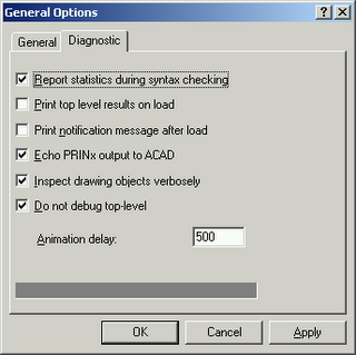
Close this dialog. Make sure the window with your code is current in the VLIDE. Now look for the "Tools" toolbar. Click on the third icon from the left (this should be "Check Edit Window").

After you click this button, the Build Window will appear in the VLIDE. In this window will be a list of all global variables.
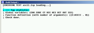
Copy this list of variables, along with the parenthesis, to your code window overwriting the single pair of parenthesis shown earlier. Add the required "/" character after the first parenthesis and then add a space after it. (The "/" character separates function arguments from local variables).
The result is shown here.
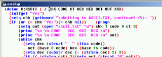
This was just a small example, but if you ever work on a large routine with dozens of variables, this tip can really help.
Labels: Programming
PermaLink Posted 7/24/2006 06:13:00 PM Comments (2)
I think this is still some good info - here are the links...
bit codes
Create a Layer List and thier current state to a file
How to determine if a point is on a polyline
Labels: Reference
PermaLink Posted 7/06/2006 06:37:00 PM Comments (0)
Sure it's easy to add a pull-down menu or toolbar, but do you know where this data lives? Do you know how to back it up? Do you know how to migrate it to your friends machine, or to a new install of the latest version?
Here are some tips of how to setup your AutoCAD customization so that it's easy to use, backup, and migrate.
The procedures below are described for AutoCAD 2006/2007, earlier versions are similar. Any items specific to 2006/2007 are marked with *.
- Create a new directory, let's call it C:\CADSTUFF
- Add this new directory to the top of your support file search path.
- Place all your custom files in this new directory.
- This might include:
- acad.lsp - this lisp file is loaded automatically at the startup of AutoCAD. This file may contain commands and operations that only need to be done once per AutoCAD session. If the system variable ACADLSPASDOC is set to 1, then this file is loaded every time a new drawing is opened. I suggest keeping ACADLSPASDOC set to 0.
- acaddoc.lsp - This lisp file is loaded automatically each time a drawing is opened. It might contain lisp routines that need to be loaded in each drawing. You can also include (setvar) commands to set system variables that are not saved in the drawing or registry.
- custom.cui - This menu file is partially loaded automatically each time AutoCAD starts *
- custom.mnl - This lisp file is loaded automatically each time custom.cui is loaded.
- acad.pgp - AutoCAD program parameters file. See AutoCAD HELP for more information.
- acad.fmp - Font mapping file. See AutoCAD HELP for more information.
- custom linetype files
- custom hatch patterns
- custom shape files
- and more...
- acad.lsp - this lisp file is loaded automatically at the startup of AutoCAD. This file may contain commands and operations that only need to be done once per AutoCAD session. If the system variable ACADLSPASDOC is set to 1, then this file is loaded every time a new drawing is opened. I suggest keeping ACADLSPASDOC set to 0.
Why add this path to the top? AutoCAD automatically loads certain files at application startup and at drawing startup. In doing so, it searchs the support file search path in the order specified. loads the first file it finds, then quits looking. For example, if you have a custom acad.pgp in C:\CADSTUFF and this path is at the top, it will be found and loaded. It doesn't matter if there are 2 or 3 other files named acad.pgp in other directories, these will not be found or loaded.
If you want to create a custom menu or toolbars, do not customize the stock "acad.cui". Why? Because your changes can be lost during the next reinstall, repair, service pack application, or upgrade that you perform. Create your own menu file and partially load it instead. As mentioned, AutoCAD will automatically partial load the menu named custom.cui (a blank one is supplied with AutoCAD) *, or you can create your own menu, like "mymenu.cui". Either way, save this new menu to your C:\CADSTUFF directory.
Now all your customization is saved in a single directory, so it's easy to back up, easy to find when edits are needed, and you don't have to worry about migrating these customizations to future releases. When that time comes, simply add C:\CADSTUFF to the top of the support file search path again.
If you work in a network environment and you want to have a single copy of these customizations for all users, then instead of making C:\CADSTUFF on your local machine, create a network share like \\MYSERVER\CADSTUFF. Then add that path to the top of everyone's support file search path. Make sure to set the network security permissions accordingly so that only the necessary persons have write access to this location.
PermaLink Posted 7/02/2006 07:27:00 AM Comments (2)
Download here
PermaLink Posted 6/14/2006 11:45:00 AM Comments (0)
Add a Textbox to your form
Position and size it to it's maximum size.
Make note of the width of the textbox when you are done.
Add the following code to your form Initialize event.
TextBox1.Width = 0
TextBox1.BackColor = vbBlue '(or the color of your choice)
Now in the procedure for which you want to show progress, follow this:
Divide the width of the textbox by the number of iterations, this is the amount by which the progress bar will grow for each iteration.
Then in your iteration loop, increment the width of the textbox by the above result.
Here is an example.
Private Sub CommandButton1_Click()
Dim i As Integer, x As Double
Dim num As Integer, start As Double
num = 150 '(this will typically be a variable in your procedure)
x = 206 / num
For i = 1 To num
'-------------------------------
' this dummy code is just to give
' the progress bar time to work
' in this example
    start = Timer
    Do While Timer < start + 0.02
        DoEvents
    Loop
' end dummy code
'-------------------------------
' This changes the progress bar
    TextBox1.Width = i * x
Next i
End Sub
num will typically already be in your procedure as the number of items in a collection or array that you are processing.
x is the width of the textbox divided by num
For i = 1 to num is just a sample loop. You will have your own.
Setting the textbox width to i * x at each iteration is what makes the "Progress Bar" actually work as shown below.

I received a very good comment from Nick Zeeben. "...the DoEvents inside the loop is rather cruical to allowing windows to break in and repaint the dialog otherwise the progress bar doesnt have a chance to redraw."
Thanks Nick.
Labels: Programming
PermaLink Posted 5/30/2006 08:12:00 PM Comments (3)
Rapid acceptance, what does this mean? Someone placed a huge new order yesterday, or that they just converted a few shops from the competition?
What are they going to say...? "sales are slow, please buy some..."?
The whole PR could have been summed up in one sentence - "We're Autodesk, we're doing well, thank you..."
Labels: Notices
PermaLink Posted 5/24/2006 07:38:00 AM Comments (0)
If you have any unexplained errors that cannot be solved by other methods, such as commands that stop working, a repair may be required also.
Here's how to do it...
- Open the Control Panel, then find the application on which to run the repair.

- Click the Change button.
- On the next screen, choose Reinstall or Repair, then the Next button.

- On the next screen, choose Repair errors in my...
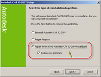
The rest of the prompts should be self-explanatory. If you original install from a CD or DVD, you will be prompted for the media. If your install from from a network deployment, you must have access to the unaltered copy of said deployment.
PermaLink Posted 5/19/2006 01:03:00 PM Comments (0)
Labels: Piracy
PermaLink Posted 5/09/2006 04:16:00 PM Comments (0)
If you have multiple AutoCAD-based products on a computer, and you uninstall one or more of the products, you must repair or reinstall the remaining products.
Many people install a new version, leaving the old version on[*] to finish up projects or whatever, and then later decide to uninstall the old version. Chances are something will not be working right in the new version after you perform this UNinstall.
Make sure to run a repair on all remaining AutoCAD based products after doing the UNinstall. To do this, open your control panel, choose Add or Remove Programs, then find the desired product. Click the Change button and follow the prompts.
Of course, this rule isn't limited to "old" and "new" versions of the same product. It would also apply for example in the case of two different products like Civil3D 2006 and Land Desktop 2006.
* Check your EULA regarding how long you can keep two versions installed.
Labels: Tips
PermaLink Posted 4/27/2006 01:21:00 PM Comments (0)
Labels: Notices
PermaLink Posted 4/27/2006 07:34:00 AM Comments (0)
The CAD Industry Blog - RSS/Atom Feed
Labels: New Blogs
PermaLink Posted 4/20/2006 08:55:00 PM Comments (0)
- Angel's Civil 3D Thoughts Blog - RSS/Atom Feed
- Civil 3D - It's Just Dirt Blog - RSS/Atom Feed
- Beneath The Lines Blog - RSS/Atom Feed
- Civil 3D - Paving the Way Blog - RSS/Atom Feed
- The Crazy World of Civil 3D Blog - RSS/Atom Feed
- Civil Solutions - Taylor Tech Blog Blog - RSS/Atom Feed
- Civil3D.com
Also if you are not aware, Autodesk presents weekly webcasts on Civil 3D. More info along with links to archived presentations can be found here: Autodesk Civil 3D Webcasts
One last note: Survey functionality is included in Civil 3D 2007
Labels: Civil
PermaLink Posted 4/08/2006 10:29:00 AM Comments (0)
First off, if someone gave you a PDF instead of a DWG, it was probably for a reason. Ask the DWG author for the DWG file. This is the easiest method, and you don't have to worry about data loss during the conversion.
If you cannot obtain the source DWG file, try these steps.
| Tool | Notes |
|---|---|
| Adobe Illustrator | Open the PDF using this software, then save as a DWG or DXF file. |
| Ghostscript & GSView | Open the PDF using this software, then export to a DXF file. |
| Adobe Acrobat | Open the PDF using this software, then use the copy graphics tool to copy the graphics to the clipboard. Then paste into AutoCAD. |
| PDFImport | This program will import a vector PDF file directly into AutoCAD. No DXF conversion needed. Raster PDF's are imported as raster images. Requires AutoCAD 2000 or later. |
| PDFConvert | This standalone windows program will convert a vector PDF file to a DXF or SCR file for use in AutoCAD or other CAD application. Does not support raster PDF's |
| PDF2CAD | This standalone windows program will convert a vector PDF file to a DXF file. |
Note that if the PDF author added security methods to the PDF, some or all of these methods may not work.
Updated 01 FEB 2007
Labels: pdf
PermaLink Posted 3/28/2006 08:47:00 PM Comments (2)
- In 2006, the command line is a dockable window similar to Properties and Sheet Set Manager, and it can be "turned off". Try typing in the command COMMANDLINE, or pressing the key combination Ctrl+9
- It may just be floating below your windows taskbar. Try repostioning the taskbar.
- Command line position, size and whether it's docked or floating is saved per workspace. Try switching to a different workspace.
- Modify your current workspace. Open the CUI editor, highlight your current workspace on the left side, and click Customize Workspace on the right side. Right below there, navigate the Dockable Windows category and click on Command Line. Just below there you will see the properties, change them as shown here:
- Show = Yes
- Orientation = Top
- Allow Docking = Yes
- Height = 200
- Width = 600
Now press Apply and OK. The command line should be docked at the top now. - Show = Yes
- If all else fails, follow these steps.
- Shut down AutoCAD and open Windows Explorer.
- Navigate to your local support directory. This will typically be: C:\Documents and Settings\<username>\Application Data\Autodesk\<autodesk product>\R16.2\enu\Support\
- From there, go into the Profiles directory.
- Look for a file named "FixedProfile.aws".
- Either rename it or move it to another location
- Restart AutoCAD
- Shut down AutoCAD and open Windows Explorer.
If you are REALLY adventurous, the properties of the Command Line are stored in the "FixedProfile.aws" file, which is XML format. I'm not suggesting to start hacking away at this file, because one of the above methods will almost surely restore your command line.
Good luck and let me know how this works for you.
Labels: Tips
PermaLink Posted 3/22/2006 06:35:00 AM Comments (1)
None of the fancy 3D stuff from full AutoCAD made it obviously, but the built-in plot to PDF will probably be a big hit.
Dynamic Block authoring is something I know many LT users have been wanting.
PermaLink Posted 3/16/2006 07:24:00 PM Comments (0)
The FREE Viewers are:
BIT-View: HPGL/2, RTL, TIFF, JPG
Oce Publisher: DWG, DXF, HPGL, HPGL/2, RTL, TIFF, CALS, DWF, PS, PDF, LDF.
The not-so-quite free ones:
SPLOT
View Companion Pro
RePlot
CERN HPGL Viewer
Fplot
EteCad
PentaLogix ViewMate
PloComp
CadSoftTools ABViewer
CadViewer (applet/API)
RxView
If you think you might want to convert a PLT file to a DWG or DXF file, check this out.
If you use any of these applications, let me know how it goes.
Labels: Viewers
PermaLink Posted 3/16/2006 07:04:00 PM Comments (4)
With all the buzz about the soon to be released AutoCAD 2007, why is this class being offered now? First off, it was requested. But secondly, if you are one of the many users that are not on 2006, then whether you upgrade to 2006, 2007, or even a future release, the features in 2006 will still be there. Imagine upgrading from R13 to 2002 and missing out on MDI or the plotting upgrades introduced in 2000.
This is my first time as an ATP instructor, so bear with me. The class handout is more of a reference guide than a 'step-by-step' tutorial on certain features. Feedback is appreciated.
Register for this course and join in. If you are not an AUGI member, there is no cost to join.
PermaLink Posted 3/14/2006 09:42:00 AM Comments (0)
Labels: Tips
PermaLink Posted 2/27/2006 01:13:00 PM Comments (3)
Error inserting TIFF files: Invalid File Format
Unable to insert or reload LZW Compressed TIF images or GIF images
Labels: Tips
PermaLink Posted 2/10/2006 11:22:00 AM Comments (0)
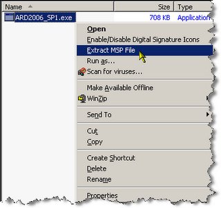
Save the following as a .REG file, then import it.
Windows Registry Editor Version 5.00

[HKEY_CLASSES_ROOT\exefile\shell\Extract MSP File]

[HKEY_CLASSES_ROOT\exefile\shell\Extract MSP File\command]
@="%1 /e %1.msp"
Now when you right click on an .exe file, you will have to option to "Extract MSP File" as shown below.
Labels: Tips
PermaLink Posted 1/18/2006 07:59:00 AM Comments (5)
Taking this one step further, you can search a whole directory, drive, or even a network for drawings containing certain named objects such as layers, blocks, layouts, and dimstyles.
Let's say you need to find a certain drawing, but you do not remember it's name or exact location. You do however know the name of a layout it contains. You can find this drawing easily.
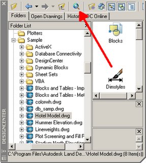
Start by opening DesignCenter (ADC at the command line or Ctrl+2 shortcut). Click the search button on top.
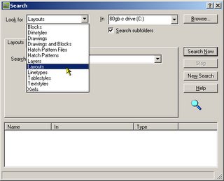
In the search dialog, select Layout in the "Look for" drop down list. Select the location in which to search. Enter the name of the layout, then click Search Now
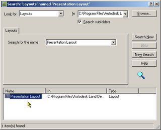
Depending on the number of drawings being searched, it may take anywhere from a few seconds to a few minutes. When the results are found, you can adjust the columns to view the full path. Double clicking on the name of the layout will load that drawing in DesignCenter.
Note that the available options in the search dialog depend on what you are searching for. Explore the search feature in DesignCenter, you may discover other time saving tricks.
Labels: Tips
PermaLink Posted 1/13/2006 08:03:00 AM Comments (0)
Here are a few direct links.
...and a few specific tips.
- Using trigonometic calculations in table formulas
- Share your custom scales
- Rounding errors in QuickCalc
- Create Polylines with Cleanup Tool
Labels: Tips
PermaLink Posted 1/03/2006 09:33:00 PM Comments (0)
